Table of Contents
Tiny_TPS (ATTiny84 Variante)
My TPS simulator includes as well as target the ATtiny84 variant. To use this version, the Arduino IDE must contain the ATtiny Core. In the Arduino IDE you must first add an additional board manager URL in the preferences. http://drazzy.com/package_drazzy.com_index.json Then you can install the ATtinyCore by Spance Konde and then select the ATtiny24 / 44/ 84 board in the board selection area. It is also important to put the pin mapping on COunterClockWise (old ATtiny Core) Now you can recompile the TPS, and program the generated code version into the Tiny with an ISP programmer.
The following assignment of the ATTiny pins to the TPS inputs / outputs applies:
| TPS Connections | Arduino related | ATtiny84 Pins | 14 Pin Layout | |||||||||
|---|---|---|---|---|---|---|---|---|---|---|---|---|
| Din1, 2, 3, 4 | D10, 9, 8, 7 | 13, 12, 11, 10 | Vcc | 1 | 14 | Gnd | ||||||
| Dout1, 2, 3, 4 | D6, 5, 4, 1 | 9, 8, 7, 3 | SW_PRG | 2 | 13 | ADC1 | RC2 | Din1 | ||||
| PWM1, 2 | D2, 3 | 5, 6 | Dout4 | 3 | 12 | ADC2 | RC1 | Din2 | TX | |||
| Servo1, 2 | D2, 3 | 5, 6 | Reset | 4 | 11 | SW_SEL | Din3 | RX | ||||
| ADC1, 2 | A0, A1 | 13, 12 | Servo1 | PWM1 | 5 | 10 | Din4 | |||||
| RC1,2 | D9, D10 | 12, 13 | Servo2 | PWM2 | 6 | 9 | Dout1 | |||||
| SW_PRG | D0 | 2 | Dout3 | 7 | 8 | Dout2 | ||||||
| SW_SEL | D8 | 11 | ||||||||||
Unfortunately, dual use of pins on the ATtiny can not be avoided, because there are only 11 pins left after deducting the power supply and reset pin. Thus, e.g. Servo and PWM can not be used simultaneously. The SEL switch is on the input 3 pin. And the two ADC inputs occupy the digital inputs D1 and D2. Pin 11 of the ATtiny is needed for the reset.
And the ATtiny is operated with internal clock at 8MHz.
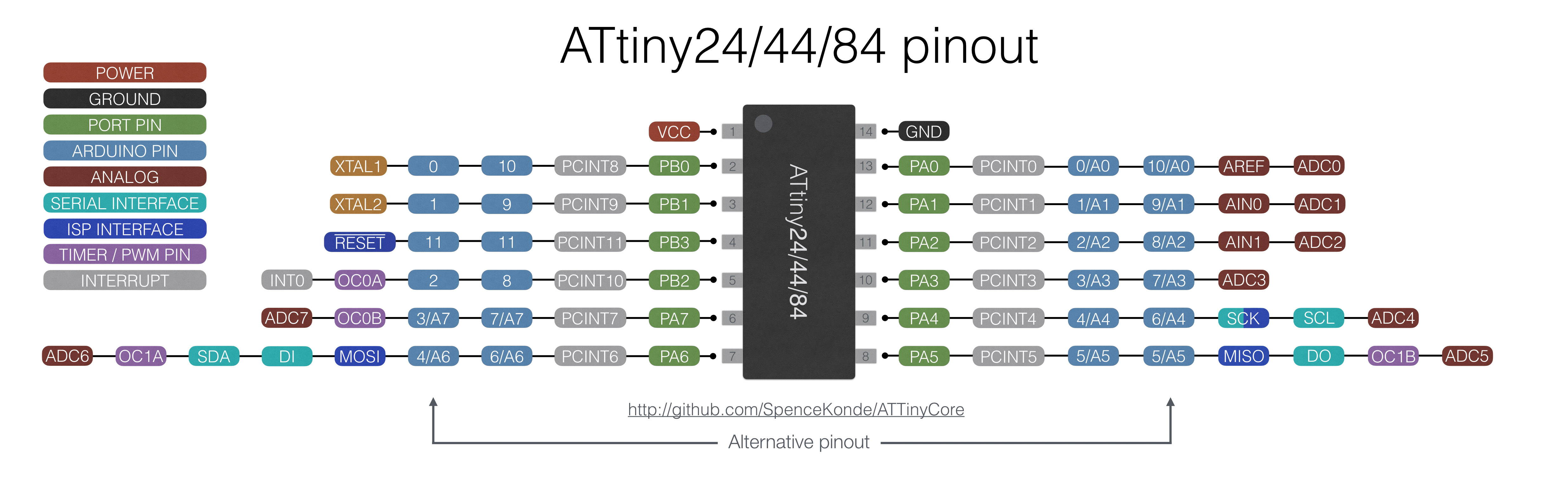
Here's the current Arduino to Pin assignment of the ATtiny core:
Schematic
here you'll find the actual schematic and layout.


Connections
All connections to the board are described here.
Analog
The analog input provide access to A/D Convert 1 and 2. The pinout is
| Pin | Signal |
|---|---|
| 1 | +5V |
| 2 | ADC1 |
| 3 | ADC2 |
| 4 | GND |
Input
Standard TPS input section with 4 inputs protected by 220 Ohm resistors.
| Pin | Signal |
|---|---|
| 1 | Din.1 |
| 2 | Din.2 |
| 3 | Din.3 |
| 4 | Din.4 |
| 5 | GND |
Output
Standard TPS output section with 4 outputs parallel to the on board low current LEDs.
| Pin | Signal |
|---|---|
| 1 | Dout.1 |
| 2 | Dout.2 |
| 3 | Dout.3 |
| 4 | Dout.4 |
| 5 | GND |
PWM
PWM Outputs. Frequency 500Hz.
| Pin | Signal |
|---|---|
| 1 | PWM1 |
| 2 | GND |
| 3 | PWM2 |
| 4 | GND |
Power
Power connector to power up the TPS and to get some regulated power from the internal 5V source. (max. 100mA)
PS: Power savings jumper, if not closed, all LEDs will be off.
| Pin | Signal |
|---|---|
| 1 | PS |
| 2 | PS |
| 3 | V+in |
| 4 | GND |
| 5 | +5V |
| 6 | GND |
Servo
There are 2 RC_Servo connections on this board.
| Pin | Signal |
|---|---|
| 1 | PWM |
| 2 | +5V |
| 3 | GND |
RC
There are two RC PWM Inputs for standard model receivers. The Pulse should be between 1ms and 2ms. The +5V pin can be powered via the internal source when the jumper A is closed. If the internal source is not wanted remove this jumper.
| Pin | Signal |
|---|---|
| 1 | PWM |
| 2 | +5V |
| 3 | GND |
Switches
The switches (or additional ones in parallel) can be placed outside as well.
| Pin | Signal |
|---|---|
| 1 | PRG |
| 2 | SEL |
| 3 | Reset |
| 4 | GND |
