Table of Contents
Raspberry Pi Pico
Introduction
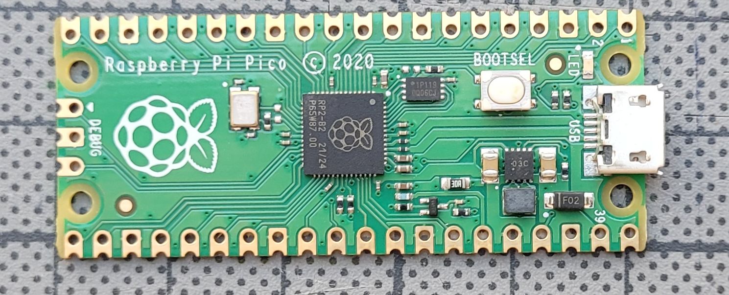
The Pico Board is only slightly larger than an Arduino Nano and has a MicroUSB interface for communication with the host. Interesting facts about this controller:
- Dual-core Arm Cortex-M0+ processor, flexible clock with up to 133 MHz (250MHz overclocking is possible)
- 264KB on chip SRAM
- 2MB onboard QSPI Flash
- 26 multifunctional GPIO pins
- 3 analogue inputs
- 2 × UART, 2 × SPI controllers, 2 × I2C controllers, 16 × PWM channels
- 1 × USB 1.1 controller
- 8 × Programmable I/O (PIO) custom state machines
Above all, the price is also an important reason. While the Arduino Nano is currently being traded at €8, the RPI Pico is available from €4.
There are several options for programming: On the one hand you can of course program the Pico with a tool chain in C++. There is also a variant for the board manager of the Arduino IDE.
On the other hand there is a MicroPython implementation on the Pico.
For TPS I decided to use a MicroPython implementation,because I already did implementations for Calliope and Microbit 1partially in MicroPython. And there is already a functioning file system connection. As the Pico has significantly more pins available, I have expanded the command set a bit: In addition, there are now 2 more analog outputs, which can also be used as servo outputs. (Only in 8-bit mode)
The current development version can be found in my Python-TPS github repo: https://github.com/willie68/PythonTPS_SPS
Command Implementation Chart
The command implementation list for the Raspberry PI Pico:
| 0 | 1 | 2 | 3 | 4 | 5 | 6 | 7 | |
|---|---|---|---|---|---|---|---|---|
| n.n. | Port [DOUT] | Delay [WAIT] | Jump back relative [RJMP] | A=# [LDA] | =A | A= | A=expression | |
| 0 | NOP [NOP] | off | 1ms | 0 | 0 | A↔B [SWAP] | ||
| 1 | 1 | 2ms | 1 | 1 | B=A [MOV] | A=B [MOV] | A=A + 1 [INC] | |
| 2 | 2 | 5ms | 2 | 2 | C=A [MOV] | A=C [MOV] | A=A - 1 [DEC] | |
| 3 | 3 | 10ms | 3 | 3 | D=A [MOV] | A=D [MOV] | A=A + B [ADD] | |
| 4 | 4 | 20ms | 4 | 4 | Dout=A [STA] | Din [LDA] | A=A - B [SUB] | |
| 5 | 5 | 50ms | 5 | 5 | Dout.1=A.1 [STA] | Din.1 [LDA] | A=A * B [MUL] | |
| 6 | 6 | 100ms | 6 | 6 | Dout.2=A.1 [STA] | Din.2 [LDA] | A=A / B [DIV] | |
| 7 | 7 | 200ms | 7 | 7 | Dout.3=A.1 [STA] | Din.3 [LDA] | A=A and B [AND] | |
| 8 | 8 | 500ms | 8 | 8 | Dout.4=A.1 [STA] | Din.4 [LDA] | A=A or B [OR] | |
| 9 | 9 | 1s | 9 | 9 | PWM.1=A [STA] | ADC.1 [LDA] | A=A xor B [XOR] | |
| a | 10 | 2s | 10 | 10 | PWM.2=A [STA] | ADC.2 [LDA] | A= not A [NOT] | |
| b | 11 | 5s | 11 | 11 | Servo.1=A [STA] | RCin.1 [LDA] | A= A % B (Rest) [MOD] | |
| c | 12 | 10s | 12 | 12 | Servo.2=A [STA] | RCin.2 [LDA] | A= A + 16 * B [BYTE] | |
| d | 13 | 20s | 13 | 13 | E=A [MOV] | A=E [MOV] | A= B - A[BSUBA] | |
| e | 14 | 30s | 14 | 14 | F=A [MOV] | A=F [MOV] | A=A SHR 1 [SHR] | |
| f | 15 | 60s | 15 | 15 | Push A [PUSH] | Pop A [POP] | A=A SHL 1 [SHL] |
| 8 | 9 | a | b | c | d | e | f | |
|---|---|---|---|---|---|---|---|---|
| Page [PAGE] | Jump absolut (#+16*page) [JMP] | C* C>0: C=C-1; Jump # + (16*page) [LOOPC] | D* D>0:D=D-1; Jump # + (16*page) [LOOPD] | Skip if | Call # + (16*Page) [Call] | Callsub/Ret | Byte Commands | |
| 0 | 0 | 0 | 0 | 0 | A==0 [SKIP0] | 0 | ret [RTR] | A=ADC.1 [BLDA] |
| 1 | 1 | 1 | 1 | 1 | A>B [AGTB] | 1 | Call 1 [CASB] | A=ADC.2 [BLDA] |
| 2 | 2 | 2 | 2 | 2 | A<B [ALTB] | 2 | 2 [CASB] | A=RCin.1 [BLDA] |
| 3 | 3 | 3 | 3 | 3 | A==B [AEQB] | 3 | 3 [CASB] | A=RCin.2 [BLDA] |
| 4 | 4 | 4 | 4 | 4 | Din.1==1 [DEQ1 1] | 4 | 4 [CASB] | PWM.1=A [BSTA] |
| 5 | 5 | 5 | 5 | 5 | Din.2==1 [DEQ1 2] | 5 | 5 [CASB] | PWM.2=A [BSTA] |
| 6 | 6 | 6 | 6 | 6 | Din.3==1 [DEQ1 3] | 6 | 6 [CASB] | Servo.1=A [BSTA] |
| 7 | 7 | 7 | 7 | 7 | Din.4==1 [DEQ1 4] | 7 | Servo.2=A [BSTA] | |
| 8 | 8 | 8 | 8 | 8 | Din.1==0 [DEQ0 1] | 8 | Def 1 [DFSB] | Tone=A [TONE] |
| 9 | 9 | 9 | 9 | 9 | Din.2==0 [DEQ0 2] | 9 | 2 [DFSB] | PWM.3=A [BSTA] |
| a | 10 | 10 | 10 | 10 | Din.3==0 [DEQ0 3] | 10 | 3 [DFSB] | PWM.4=A [BSTA] |
| b | 11 | 11 | 11 | 11 | Din.4==0 [DEQ0 4] | 11 | 4 [DFSB] | Servo.3=A [BSTA] |
| c | 12 | 12 | 12 | 12 | S_PRG==0 [PRG0] | 12 | 5 [DFSB] | Servo.4=A [BSTA] |
| d | 13 | 13 | 13 | 13 | S_SEL==0 [SEL0] | 13 | 6 [DFSB] | LED On [LED1] |
| e | 14 | 14 | 14 | 14 | S_PRG==1 [PRG1] | 14 | LED off [LED0] | |
| f | 15 | 15 | 15 | 15 | S_SEL==1 [SEL1] | 15 | restart [REST] | PrgEnd [PEND] |
Hardware assignments
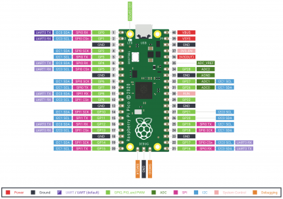
Pin Mapping Table
| pin number | pico function | TPS function | pin | pico function | TPS function |
| ———- | ————– | ———— | —- | ————- | ————— |
| 1 | GP0 | 40 | VBUS | ||
| 2 | GP1 | 39 | VSYS | ||
| 3 | GND | 38 | GND | ||
| 4 | GP2 | Dout.1 | 37 | 3V3_EN | |
| 5 | GP3 | Dout.2 | 36 | 3V3 | |
| 6 | GP4 | Dout.3 | 35 | ADC_VREF | |
| 7 | GP5 | Dout.4 | 34 | ADC2 | |
| 8 | GND | 33 | GND | ||
| 9 | GP6 | Din.1 | 32 | ADC1 | ADC.1 |
| 10 | GP7 | Din.2 | 31 | ADC0 | ADC.0 |
| 11 | GP8 | Din.3 | 30 | RUN | Reset |
| 12 | GP9 | Din.4 | 29 | GP22 | |
| 13 | GND | 28 | GND | ||
| 14 | GP10 | SEL | 27 | GP21 | PWM.4 (Servo.4) |
| 15 | GP11 | PRG | 26 | GP20 | PWM.3 (Servo.3) |
| 16 | GP12, UART0 TX | 25 | GP19 | ||
| 17 | GP13, UART0 RX | 24 | GP18 | Tone output | |
| 18 | GND | 23 | GND | ||
| 19 | GP14 | RC.1 | 22 | GP17 | PWM.2 (Servo.2) |
| 20 | GP15 | RC.2 | 21 | GP16 | PWM.1 (Servo.1) |
Installation
Currently the installation is a bit more complex. But I am working on it. Therefore, the Thonny IDE must currently be installed on the host. (https://thonny.org/)
- Unordered List ItemFirst, download the Github repo (https://github.com/willie68/PythonTPS_SPS) as a ZIP and unpack it into a subdirectory of your choice.
- then go to the subdirectory picoTPS and there in the directory Firmware. Here are the various RPI Pico firmwares.
- Now plug in the Pico while holding down the BOTSSEL button. A new drive will appear in Explorer.
- Now copy the file to this drive: rp2-pico-###########.uf2, wait for the restart
- Next you can start your Thonny IDE and connect to the RPI Pico.
- Then open the main.py from the PicoTPS directory and load it onto the Pico.
- Finished


