Inhaltsverzeichnis
Tiny_TPS (ATTiny84 Variante)
In meiner TPS Version ist eine ATtiny84 Variante enthalten. Tiny_TPS. Um diese Version zu benutzen, muss die Arduino IDE den ATtiny Core enthalten. In der Arduino IDE muss man zunächst in den Voreinstellungen eine zusätzliche Boardverwalter URL hinzufügen. http://drazzy.com/package_drazzy.com_index.json
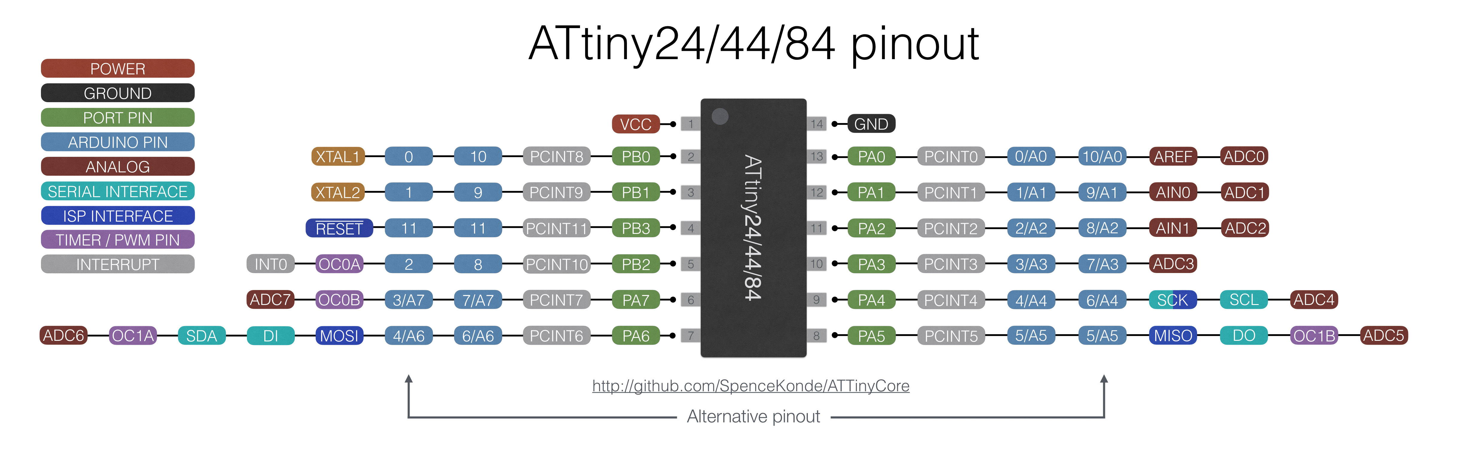
Dann kann man den ATtinyCore by Spance Konde installieren und dann in der Boardauswahl das ATtiny24/44/84 Board auswählen. Wichtig ist auch noch das Pinmapping auf CounterClockWise zu stellen (old ATtiny Core) Jetzt kann man die TPS neu compilieren und mit einem ISP Programmer die Version in den Tiny programmieren.
Folgende Zuordnung der ATTiny Pins zu den TPS Ein/Ausgängen gilt:
| TPS Anschlüsse | Arduino Zuordnung | ATtiny84 Pins | 14 Pin Layout | |||||||||
|---|---|---|---|---|---|---|---|---|---|---|---|---|
| Din1, 2, 3, 4 | D10, 9, 8, 7 | 13, 12, 11, 10 | Vcc | 1 | 14 | Gnd | ||||||
| Dout1, 2, 3, 4 | D6, 5, 4, 1 | 9, 8, 7, 3 | SW_PRG | 2 | 13 | ADC1 | RC2 | Din1 | ||||
| PWM1, 2 | D2, 3 | 5, 6 | Dout4 | 3 | 12 | ADC2 | RC1 | Din2 | TX | |||
| Servo1, 2 | D2, 3 | 5, 6 | Reset | 4 | 11 | SW_SEL | Din3 | RX | ||||
| ADC1, 2 | A0, A1 | 13, 12 | Servo1 | PWM1 | 5 | 10 | Din4 | |||||
| RC1,2 | D9, D10 | 12, 13 | Servo2 | PWM2 | 6 | 9 | Dout1 | |||||
| SW_PRG | D0 | 2 | Dout3 | 7 | 8 | Dout2 | ||||||
| SW_SEL | D8 | 11 |
Leider lassen sich doppelte Verwendungen von Pins auf dem ATtiny nicht verhindern, da dort nach Abzug von Spannungsversorgung und Resetpin nur 11 Pins übrig bleiben. So können z.B. Servo und PWM nicht gleichzeitig benutzt werden. Der SEL Switch liegt mit auf dem Eingang 3. Und auch die beiden ADC Eingänge belegen die digitalen Eingänge D1 und D2.
Pin 11 des ATtiny wird für den Reset benötigt. Und der ATtiny wird mit internem Takt bei 8MHz betrieben.
Hier gibt's die aktuelle Arduino zu Pin Zuordnung des ATtiny-Cores:
Schematic
Hier mal der aktuelle Schaltplan und das Layout:


Connections
All connections to the board are described here.
Analog
The analog input provide access to A/D Convert 1 and 2. The pinout is
| Pin | Signal |
|---|---|
| 1 | +5V |
| 2 | ADC1 |
| 3 | ADC2 |
| 4 | GND |
Input
Standard TPS input section with 4 inputs protected by 220 Ohm resistors.
| Pin | Signal |
|---|---|
| 1 | Din.1 |
| 2 | Din.2 |
| 3 | Din.3 |
| 4 | Din.4 |
| 5 | GND |
Output
Standard TPS output section with 4 outputs parallel to the on board low current LEDs.
| Pin | Signal |
|---|---|
| 1 | Dout.1 |
| 2 | Dout.2 |
| 3 | Dout.3 |
| 4 | Dout.4 |
| 5 | GND |
PWM
PWM Outputs. Frequency 500Hz.
| Pin | Signal |
|---|---|
| 1 | PWM1 |
| 2 | GND |
| 3 | PWM2 |
| 4 | GND |
Power
Power connector to power up the TPS and to get some regulated power from the internal 5V source. (max. 100mA)
PS: Power savings jumper, if not closed, all LEDs will be off.
| Pin | Signal |
|---|---|
| 1 | PS |
| 2 | PS |
| 3 | V+in |
| 4 | GND |
| 5 | +5V |
| 6 | GND |
Servo
There are 2 RC_Servo connections on this board.
| Pin | Signal |
|---|---|
| 1 | PWM |
| 2 | +5V |
| 3 | GND |
RC
There are two RC PWM Inputs for standard model receivers. The Pulse should be between 1ms and 2ms. The +5V pin can be powered via the internal source when the jumper A is closed. If the internal source is not wanted remove this jumper.
| Pin | Signal |
|---|---|
| 1 | PWM |
| 2 | +5V |
| 3 | GND |
Switches
The switches (or additional ones in parallel) can be placed outside as well.
| Pin | Signal |
|---|---|
| 1 | PRG |
| 2 | SEL |
| 3 | Reset |
| 4 | GND |
